800 Watt 4-Channel Amplifier T8004
800 Watt 4-Channel Amplifier T8004
The T8004 offers tremendous flexibility when wiring multiple speakers since it’s designed for lower impedance loads. A natural for powering component speakers, you can also bridge the rear channels to add a 4-ohm DVC subwoofer. A capacitor is recommended.
FEATURES AT A GLANCE
- 2-Year Warranty
- Stealth Connections
- 1/0 Gauge power/ground connectors with ANL fusing
- 12dB or 24dB/octave selectable crossover
- Infrasonic filter
- Best in class 4 oz. copper traces
- 2/4 channel input switch
- Audiophile grade speaker connections

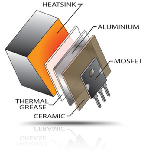
Rockford Fosgate amps use MEHSA, a thermal substrate that maximizes heat transfer between MOSFET power devices ...
Learn more
MEHSA
Rockford Fosgate amps use MEHSA, a thermal substrate that maximizes heat transfer between MOSFET power devices and heat-sink. The MEHSA substrate is so efficient at reducing MOSFET temperatures, it lowers distortion, increases durability and results in a prolonged life span.
Increased open space minimizes thermal hot-spots and reduces heat through balanced power distribution.
Learn moreThermal Design Stage-2
Increased open space minimizes thermal hot-spots and reduces heat through balanced power distribution.
Para-Punch Bass EQ improves Jim Fosgate's original design by adding a 35-70Hz variable frequency center.
Learn morePara-Punch EQ
Para-Punch Bass EQ improves Jim Fosgate's original design by adding a 35-70Hz variable frequency center.
NOMAD is a "real time" analog computer that protects your amplifier from shorting speaker wires and ...
Learn moreNOMAD
NOMAD is a "real time" analog computer that protects your amplifier from shorting speaker wires and dangerously low speaker impedances.
These Avatars are a personal signature from the Rockford Fosgate team member(s) who designed and engineered ...
Learn moreEngineered In The USA
These Avatars are a personal signature from the Rockford Fosgate team member(s) who designed and engineered this fanatic product. This statement illustrates our commitment to being Designed and Engineered in the U.S.A.

Power ratings on Rockford Fosgate amplifiers conform to CTA-2006 industry standards. These guidelines mean your amplifier's ...
Learn more
CTA-2006 Compliant
Power ratings on Rockford Fosgate amplifiers conform to CTA-2006 industry standards. These guidelines mean your amplifier's output power ratings are REAL POWER numbers, not inflated marketing ratings.
DSM utilize 1% tight-tolerances improving efficiency of the circuit, decreases cross-talk from other discrete components and ...
Learn moreDSM
DSM utilize 1% tight-tolerances improving efficiency of the circuit, decreases cross-talk from other discrete components and lowers operating temperature.
Rockford Fosgate's thermal design results in 5 times greater heat dissipation keeping internal components running cooler ...
Learn moreThermal Design
Rockford Fosgate's thermal design results in 5 times greater heat dissipation keeping internal components running cooler and increasing performance and reliability.
(left-OLD | right-NEW)
Rockford Fosgate amps use custom TO-247 MOSFETs. These have 60% more ...
TO-247 MOSFETs
(left-OLD | right-NEW)
Rockford Fosgate amps use custom TO-247 MOSFETs. These have 60% more metal tab area for more power capacity, lower impedance and improved heat dissipation over traditional TO-220 MOSFETs found in competitor amps.
(Sum of Rated Power)
(RMS Continuous Power)
100 Watts x 4 @ 2-Ohm
200 Watts x 4 @ 1-Ohm
200 Watts x 2 @ 4-Ohm Bridged
400 Watts x 2 @ 2-Ohm Bridged
(Pvc/Powercube®)
Input switch: 2/4 ch.
Preamp Output Crossover: HP/AP/LP 12db/Octave Butterworth
Low-Pass (LP): 40-4kHz 12db or 24db/Octave Linkwitz-Riley
10x crossover switch
Infrasonic filter: 27Hz 12db/Octave
Thermal Status
Speaker Protection
(Not Included)
6.6 x 32.5 x 58.4 (cm)
(11.8 Kg.)
Knowledge Base Articles
- 2004/2005 Power series amplifiers - owner's manual
- Power Series amplifier secure fuse - service advisory
Show all Knowledge Base topics
Ask Our Experts
Return Authorization
Contact the Authorized Rockford Fosgate Dealer you purchased this product from. If you need further assistance, call 1-800-669-9899 for Rockford Customer Service. You must obtain an RA# (Return Authorization number) to return any product to Rockford Fosgate. You are responsible for shipment of product to Rockford.
Be first to hear about the latest products.
Sign up for product updates.
